
Product Description
1.1Optical Encoder:
The optical rotary encoder is a speed displacement sensor integrating opto-mechanical technology. When the rotary encoder shaft drives the grating disc to rotate, the light emitted by the light-emitting element is cut into intermittent light by the slit of the grating disc, and is received by the receiving element to generate an initial signal. After the signal is processed by the subsequent circuit, a pulse or code signal is output.

1.2Magnetic Encoder:
The main part of the magnetic encoder is composed of a magnetoresistive sensor, a magnetic drum, and a signal processing circuit. The magnetic drum is recorded into small magnetic poles at equal intervals. After the magnetic poles are magnetized, a periodically distributed spatial leakage magnetic field is generated during rotation. The magnetic field can output pulse or code signals after being processed by the DSP chip.

2. Incremental encoder and absolute encoder:
Encoders can be divided into two types: incremental and absolute
2.1Incremental encoder
When the incremental encoder shaft rotates, there is a corresponding phase pulse output. The determination of the direction of rotation and the increase or decrease of the number of pulses need to be realized with the help of the direction circuit and counter at the rear. The counting starting point can be set arbitrarily, and unlimited accumulation and measurement of multiple turns can be realized. It is also possible to use the Z signal for each pulse transmitted as the zero position of the reference machine. In addition, it is worth mentioning that sine wave encoders also belong to the category of incremental encoders. The main difference is that the output signal is a sine wave analog signal instead of a square wave digital signal. Its appearance is mainly to meet the needs of the dynamic characteristics of motor feedback.

2.2Absolute encoder
When the absolute encoder shaft rotator is used, the code corresponding to each position (binary, gray code, BCD code, etc.) is output, and the positive and negative direction and the position of the displacement can be judged from the change of the code size, without the need for a direction judgment circuit . It also has an absolute zero code. When the power is cut off or turned off and then restarted, the code can still be read out and the zero code can be accurately found. The measurement range can be n×(0~360°).

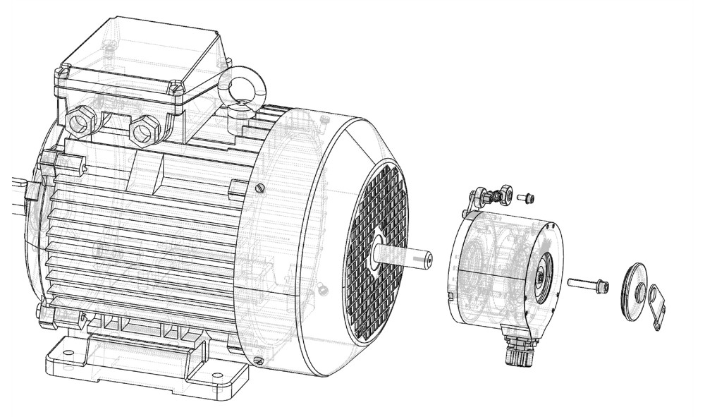
3.Installation form:
Rotary encoders are distinguished according to the installation form, which can be divided into shaft type installation and sleeve shaft type installation.
3.1On-axis installation
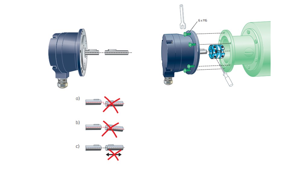
3.2Sleeve installation
4.The output form:
The electrical output form of the rotary encoder is usually: analog current/voltage signal; PNP signal; NPN signal; open collector signal; HTL (push-pull) signal; TTL (compatible with RS422 long-line drive protocol) signal; Sin/Cos Zhengxuan Wave signal; SSI synchronous serial digital signal; multiple bus communication protocol signal; optical fiber signal.
4.1Diagram of common incremental pulse output signals


4.2 SSI protocol diagram
4.2.1Protocol
| Parameter | Symbol | Min. | Typ. | Max. | Unit | Note |
| Clock period | tcL | 0.25 | 2X0 | |1S | ||
| Clock high | tcHI | 0.1 | tni | |1S | ||
| Clock low | tcLO | 0.1 | tm | |1S | ||
| Monoflop time | tm | 15 | 19 | 25 | pis |

The user obtains the current position information by sending continuous pulses to the encoder. At the first falling edge (position ①), the encoder stores the current position announcement information. At the first rising edge (position ②), the most significant bit of data is output through the data line (Dak). At each rising edge of the subsequent clock signal, the next bit of data will be output through the data line (Data). When reading data, the time of tcHI and tcLO should be less than tmMin. After the low effective bit of the data is output (position ③), the data line (Data) outputs a low level.
4.2.2Output mode
4.2.2.1、Single data output mode(SS)
①General reading When a data transmission is completed, you need to wait for tm time (the level of the data line (Data) changes from low to high). Then a new data transmission is started. The implementation method is as follows (take 12bH resolution as an example) =

4.2.2.2、Continuous data output mode(SF)
The continuous data output mode speeds up the data reading speed. When using this mode, it is necessary to continuously send clock pulses to the encoder, and there is a low level of one clock cycle between two adjacent data. The realization method is as follows (take 12bit resolution as an example).

4.3Output circuit diagram

5. Industry case:
1. HS35AY1CX15
Avtron incremental encoder with high temperature resistance up to 100 ℃ and impact resistance for speed feedback of straightening motor in metallurgical billet steelmaking process
2. HS35AY1FWU0A905ZA
AVTRON incremental encoder with high temperature resistance up to 100℃ and impact resistance for speed feedback of auxiliary drive motor for metallurgical wire rod rolling process
3. HS35MY83VU1A84ZA
Metallurgical solution process tension control motor speed feedback, HTL signal distance transmission up to 600 meters, impact-resistant AVTRON incremental encoder
4. HS35MYY6FWU0AA91ZA
Non-ferrous metal cold rolling process, flatness control motor speed and position feedback with redundant output, shock-resistant AVTRON incremental encoder
5. XR45FAYXX7LFA004
A zone explosion-proof, low-temperature and impact-resistant AVTRON incremental encoder for speed feedback of the main drive motor of the oil rig process
6. AV45AHASAS6P3A6ZA
AVTRON incremental encoder with redundant output for speed feedback of main drive motor in metallurgical galvanizing process, high temperature resistance up to 100℃, impact resistance
7. 8.H120.400A.1024.CN112 Metallurgical high-speed bar steel rolling process main drive motor speed feedback signal transmission distance up to 300 meters, high-precision, impact-resistant KUBLER incremental encoder
8. RKEAS63B10S13M12HB-R5
Reckon absolute encoder with high protection up to IP69K, programmable and impact resistance for automatic position feedback of metallurgical rail and beam rolling process